CAD to fabrication: accelerating project lifecycles with real-time drawing office integration
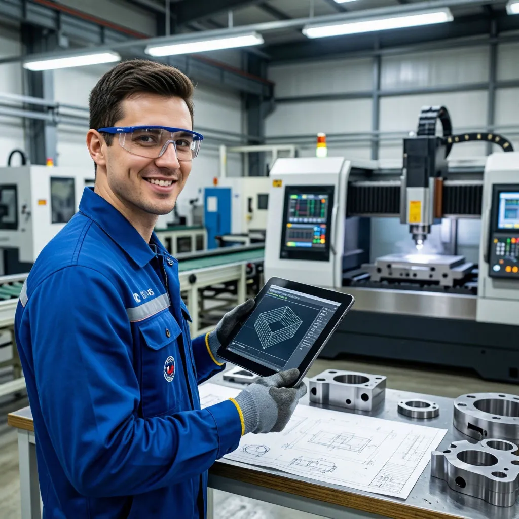
In the high-stakes arena of commercial construction and industrial engineering, the journey of a structural steel beam from a conceptual sketch to a load-bearing column is fraught with potential missteps. Historically, the drawing office and the fabrication workshop operated as two separate kingdoms, divided by a chasm of paper blueprints, manual measurements, and fragmented communication. When a draftsman made a minor revision in isolation, the change rarely trickled down to the workshop floor in time, resulting in mismatched bolt holes, incorrect beam lengths, and expensive on-site rectifications. Today, the demands of fast-track project delivery have made this disjointed approach completely obsolete. Achieving profitability and speed requires a unified digital ecosystem where data flows seamlessly, ensuring that what is designed on the screen is exactly what is built in the shop.
The evolution of drafting: from manual sketch to intelligent model
The transition from manual drafting boards to computer-aided design completely revolutionized the structural steel industry. Early digital platforms, while far superior to pencil and vellum, still functioned primarily as digital drawing boards, producing flat, two-dimensional representations of complex three-dimensional structures. While these drawings looked clean, they lacked any underlying data, leaving the fabricator with the task of manually interpreting the relationships between intersecting members.
The real breakthrough came with the introduction of parametric modeling software specifically tailored for the steel industry. Tools like AutoCAD, when paired with specialized StruCAD drafting services, allowed detailers to build intelligent, three-dimensional digital twins of entire buildings. In these advanced models, every steel section, gusset plate, bolt, and weld is represented not just as a set of lines, but as an object with distinct physical properties, material grades, and spatial coordinates. This shift from simple drawing to intelligent modeling laid the foundation for the modern, integrated fabrication pipeline.
Transforming raw data into physical structures on the shop floor
The ultimate goal of any structural steel design CAD program is to streamline the transition from design to physical reality. In an integrated environment, the 3D model generated by the drawing office does not simply serve as a visual reference; instead, it acts as the primary data source for the entire manufacturing process. This direct connection is often referred to as the CAD design to manufacture pipeline, and it has fundamentally changed how fabricators manage material preparation and cutting.
When the detailing team finalizes the 3D model, the software automatically generates CNC data files containing precise coordinates for every cut, notch, and bolt hole. These files are transferred directly to the workshop’s automated machinery, including plasma cutters, band saws, and robotic welding stations. By eliminating the need for manual marking and layout on the physical steel, this digital transfer ensures that the finished component matches the design model down to the millimeter.
Structural benefits of real-time drawing office integration
Integrating the design phase directly with the shop floor completely transforms how engineers and fabricators collaborate. By breaking down the traditional barriers between the drawing board and the cutting torch, companies can unlock several critical operational advantages:
- Automated material takeoff: generating instant, exact bills of materials directly from the 3D model, eliminating manual calculation errors.
- Seamless collision checking: identifying physical interference between beams, bracing, and connection plates before any steel is cut.
- Direct CNC machinery linkage: exporting digital files directly to automated drilling and sawing lines, bypassing manual layout processes.
- Enhanced revision tracking: ensuring that any modification made by the architect is immediately visible to the fabrication team on the shop floor.
- Optimized shipping logistics: grouping structural components within the model to plan transport phases and on-site assembly sequences.
These interconnected capabilities ensure that the drawing office acts as the brain of the entire production process. When these systems operate in harmony, the probability of executing an incorrect design on the workshop floor drops to virtually zero, allowing the fabricator to maintain an uninterrupted workflow.
Analyzing the efficiency gains of modern fabrication pipelines
To fully appreciate the business case for digital alignment, one must contrast the modern workflow with the fragmented legacy methods that historically dominated the engineering sector. The comparison below illustrates how the transition to an integrated digital pipeline impacts key project milestones, from initial drafting to final handback:
| Project phase | Traditional siloed workflow | Integrated CAD-to-fabrication system |
|---|---|---|
| Data transmission | Manual printing and mailing of paper blueprints | Direct export of digital files to production machinery |
| Clash detection | Visual inspection of 2D drawings during assembly | Automated algorithmic checks within the 3D model |
| Material optimization | Manual linear nesting calculations with high waste | Automated software nesting maximizing raw steel utilization |
| Response to revisions | Redrawing sheets manually and reissuing documents | Parametric updates propagating through the entire model |
| Quality assurance | Manual tape-measure inspections on the shop floor | Laser scanning and digital template matching |
| Assembly speed | Slow; requires frequent clarification and adjustments | Rapid; components fit together perfectly like a puzzle |
This comparison highlights why progressive fabricators are abandoning fragmented communication channels in favor of unified digital platforms. By automating the transfer of geometric data, companies can bypass the administrative bottlenecks that frequently delay the commencement of physical manufacturing.
Eliminating the costly margin of error in assembly
One of the most significant financial drains on any structural steel project is the cost of on-site modifications. When a massive steel frame is delivered to a construction site and fails to fit together, the consequences are disastrous. Cranes stand idle, installation crews are left waiting, and specialized welders must be brought in to modify the steel under less-than-ideal field conditions. These field fixes are exponentially more expensive than corrections made in a controlled factory environment.
Real-time drawing office integration mitigates this risk by hosting virtual trial assemblies within the software. Before a single steel section is fabricated, the modeler can run automated clash-detection algorithms to verify that every connection is physically viable. Furthermore, if the site team utilizes 3D laser scanners to capture the exact coordinates of the existing concrete foundations, this data can be imported directly back into the CAD software, allowing the detailing team to adjust the steelwork to accommodate any real-world foundation deviations.
Implementing a seamless digital detailing strategy
Transitioning to an integrated digital ecosystem requires more than just purchasing modern software; it demands a cultural and operational shift across the entire engineering department. To successfully bridge the gap between initial concept and physical output, organizations must execute a series of critical preparatory steps:
- Standardize the modeling protocols: establish uniform naming conventions and detailing standards across all AutoCAD and StruCAD files.
- Integrate ERP software: link the drawing office directly with inventory management programs to track material availability in real-time.
- Train shop floor operators: educate machine operators on how to read and execute digital fabrication files directly from the CNC consoles.
- Establish feedback loops: create a direct channel for fabricators to report modeling anomalies back to the detailing team for instant correction.
- Implement laser scanning: utilize 3D reality capture to verify existing site dimensions before finalizing the fabrication drawings.
Executing this phased implementation strategy ensures that the technology is supported by robust human processes. Once these operational foundations are firmly established, the organization can scale its output without risking the quality or accuracy of its structural deliveries.
Conclusion
The future of structural steel fabrication belongs to those who treat design and manufacturing not as separate departments, but as a single, continuous stream of digital data. By investing in advanced structural steel design CAD systems and fostering real-time drawing office integration, contractors can eliminate the historical disconnects that drive up project costs. This digital synergy not only protects the client’s budget and accelerates delivery times but also elevates the quality of the finished structure, ensuring that every project is built to stand the test of time.