Implementing BIM level 2 in structural steel design: eliminating clashes and rework
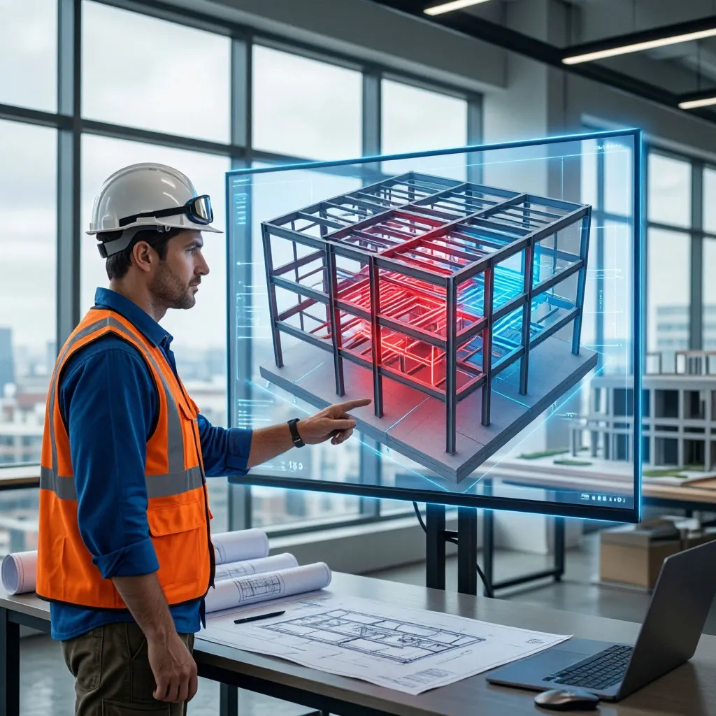
The days of paper-based construction coordination are long gone. Historically, the architectural design, structural calculations, and mechanical layouts of a building were developed in isolation, with coordination meetings relying on overlapping translucent drawings to spot physical conflicts. This fragmented approach often led to critical design errors being discovered only when heavy structural components arrived on the active job site. Today, modern digital engineering techniques have transformed this chaotic process, replacing traditional drawings with a single, highly coordinated, and intelligent digital environment that unites all design disciplines.
The collaborative environment of modern structural engineering
At the center of this digital revolution is a structured approach to sharing information known as BIM Level 2. This methodology mandates that all design parties—architects, structural analysts, and steel fabricators—create their own independent 3D models using standardized file formats that can be easily merged. Rather than working in isolation, these parties collaborate within a shared online space called a common data environment (CDE), which serves as the single source of truth for all project data.
This high level of integration ensures that any change made by one designer is instantly visible to all other participants on the team. By working within a highly integrated, collaborative 3D design workflow, engineering firms can significantly improve their overall project coordination. The primary benefits of working within a shared data environment include:
- real-time model updates: eliminating the risk of team members working with outdated or superseded drawing revisions;
- standardized data exchange: using open formats like IFC to share models seamlessly across different software platforms;
- clear digital ownership: assigning clear responsibilities and tracking changes with detailed digital audit trails;
- centralized document control: hosting all drawings, calculations, and materials certificates in one secure online location.
By organizing the project around these structured data-sharing habits, engineering firms can prevent the communication gaps that traditionally led to costly errors on the job site. This digital clarity ensures that everyone on the team is working toward the exact same construction goals, with full visibility over how their decisions affect other disciplines. Once the individual models are successfully merged in the shared database, the design team can deploy powerful automated tools to spot physical conflicts.
Eliminating physical conflicts through automated clash detection
One of the most valuable aspects of using an integrated model is the ability to run automated spatial audits before any physical materials are purchased or cut. In traditional construction, discovering that a heavy steel beam blocks a main ventilation duct or collides with a concrete wall required emergency structural changes on-site, which typically resulted in significant delays and expensive material waste. Using advanced digital coordination tools, these physical conflicts can be identified and resolved during the early planning stages.
To understand the scope of these digital audits, it is helpful to look at the different types of spatial conflicts that coordinate software can identify. This comparison shows how automated clash detection steelwork processes categorize and prioritize different physical and spatial issues during the design phase:
| Clash category | Structural conflict scenario | Digital detection mechanism | Typical engineering resolution |
|---|---|---|---|
| Hard clash | A primary steel beam physically intersects a concrete column | Geometric overlap detection in the merged 3D model | Repositioning the beam or modifying the column design |
| Soft clash | A high-voltage cable tray is routed too close to a hot steam pipe | Clearance zone violation checking | Adjusting the routing layout to maintain safe distances |
| 4D/Workflow clash | A steel frame cannot be physically erected because a concrete slab is already in place | Construction sequence simulation over time | Rescheduling the installation steps in the project timeline |
| Duplicate clash | Two identical steel joints are modeled in the exact same physical space | Component ID audit in the model database | Deleting the duplicate object from the structural model |
Identifying these different types of spatial conflicts early allows the project team to address them systematically before construction begins. Rather than rushing to find solutions during active crane lifts on-site, engineers can resolve these issues at a computer screen, where modifications cost nothing more than a few clicks. This digital coordination shifts the pressure of problem-solving away from the active construction zone and into a controlled office environment.
The physical benefits of digital precision on the construction site
When a structural steel model is fully coordinated and free of clashes, the benefits are felt directly on the active construction site. Because the steel fabricator works from the exact same digital model used by the architect and the services engineer, every beam, bracket, and bolt hole is manufactured with millimeter-level accuracy. This precision completely eliminates the need for emergency cutting, welding, or drilling on-site, which is often slow, expensive, and difficult to verify under field conditions.
Transitioning a project from initial design to successful on-site erection using a digital workflow requires a clear, step-by-step coordination process. This structured sequence ensures that all models are thoroughly reviewed and approved before manufacturing begins. The standard workflow for coordinating structural steel design includes:
- Establish modeling guidelines: define the leveling of detail and naming conventions for all project participants;
- Build individual discipline models: create the independent architectural, structural, and mechanical models;
- Merge models in the CDE: upload the files to the shared database to create a single federated model of the building;
- Run automated clash audits: use coordination software to identify physical conflicts between the different models;
- Resolve conflicts collaboratively: hold regular digital coordination meetings to review clashes and assign resolutions;
- Export fabrication-ready drawings: generate precise shop drawings directly from the coordinated 3D model for manufacturing.
Following this disciplined process ensures that the physical steelwork arrives on-site ready to be bolted together like a precision-engineered puzzle. This smooth installation process significantly lowers labor costs, reduces the need for expensive crane hire, and ensures that the project remains on schedule and within budget.
Embracing the future of structural steel design
Integrating BIM structural steel design practices is no longer just a futuristic ambition: it is an essential requirement for delivering complex modern buildings successfully. By collaborating within a shared data environment and utilizing automated clash detection, engineering firms can eliminate the errors, delays, and reworks that have traditionally plagued the construction sector. In a highly competitive industry where profit margins are tight and project timelines are demanding, embracing BIM level 2 engineering UK standards is the most effective way to ensure project success.